Home
January 2017 - K9AY Comb Generator
I've been using zener diode noise generators for years. They are a useful device for producing wide band noise. I've used this for testing filters and with antenna noise bridges. Simple zener diode based noise generators suffer fall off in level over the HF bands and I rather fancied trying something with a more constant output.
To that end I experimented with some circuits based on monothlythic amplifiers and I may return to those later. While re-reading my collection of QRP Quarterly, I found a design by Gary Breed K9AY for a simple "comb generator". It was in the summer 2009 issue and you can order back issues or the DVD compilation from QRP ARCI.
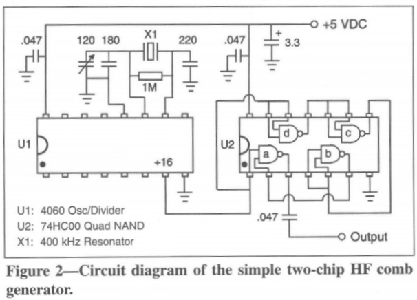
On power up my oscilloscope showed it was all working...
... except that it wasn't properly. The output was 321 kHz - not the 25 kHz it was supposed to be. Changing the ceramic resonator didn't help so I started googling for further knowledge - and found this document. Specifically, the clue was on page 14. Apparently ceramic resonators are known for going off at harmonic frequencies. The author suggested that capacitance around the ceramic resonator should be increased. So I added 100pF to the capacitor connected to pin 10 of the 4060 oscillator chip.
That was enough to make it oscillate correctly on power up, but when switched to the 1 MHz crystal position (that I had added) and then back, the resonator misbehaved again. Another 100pF fixed it.
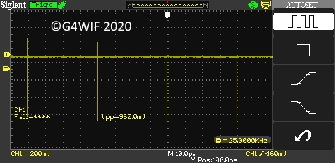
So it would seem that Gary's resonator and mine weren't quite the same and I had to modify his circuit. The resonator that you buy might need similar adjustments - or maybe none.
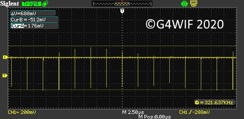
The 16 MHz crystal (for 1 MHz output) isn't bang on but close enough...
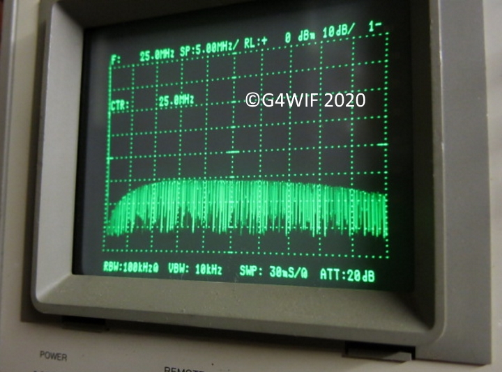
K9AY says that the comb generator "creates S9+ signals every 25 kHz from low frequencies to well beyond 30 MHz". He is being too modest because his design is much better than that and goes "very far beyond 30 MHz".
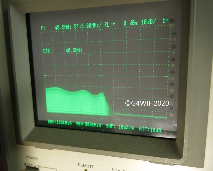
The spectrum analyser screenshot below is centred on 25 MHz with 5 MHz horizontal divisions. So you can see that there is a useful output way beyond the HF bands.
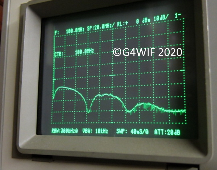
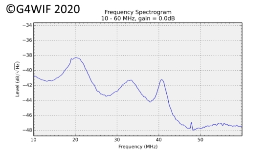
This other shot shows output to 180MHz with low points at 80MHz and 125MHz. This was a max signal trace to show more clearly the signal levels.
The printed circuit board was made "muppet style" - a process made famous by Chuck Adams K7QO. He has a superb tutorial here.
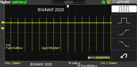
To vary the output I have added some switched attenuators to the K9AY design - which has as its signal source a 400 kHz ceramic resonator to provide 25 kHz signals (once divided down by the simple circuit).
I also added a 16 Mhz crystal to give me the alternative of 1 MHz signals via a switch. The attenuators provide 3dB and 10dB reduction in signal and the resistor values came from an article in September 1982 issue of QST. If you don't have the precise resistors in your junk box for the attenuator then this parallel resistor calculator will get you close.
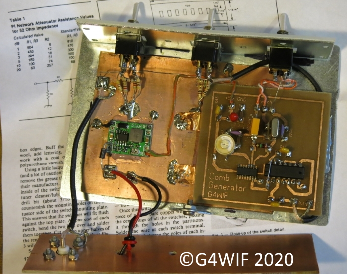
The small (left hand side) printed circuit board which the red and black power leads attach to is a very inexpensive switched mode "buck converter". This takes the 12 volt input and provides the 5 volt supply to the generator. There is an idiot diode in the supply in the event of one of those senior moments when the leads get reversed.
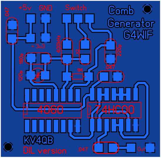
This is the double sided printed circuit board etched using the toner transfer method.
Due to the way I designed the board, it must be double sided with connections to the reverse side ground plane. I've indicated in the Sprint Layout file where those connections are made.
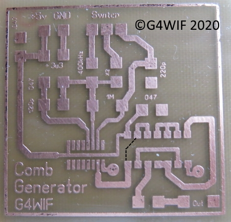
You can see a black dotted line where I missed a track!
The more observant might notice that the 4060 chip is surface mount while the 74HC00 is D.I.L.
There is no special reason why I chose those package formats - other than when I ordered the chips, these were what was available at the right price and delivery time. The muppet building method is essentially surface mount and few of us older home constructors couldn't benefit from a decent bench magnifier anyway!
The printed circuit board file that will enable you to etch your own board (muppet style) has the missing track fixed.
I've been asked to provide the gerber files so the boards can be commercially etched. These are provided below but you need to inspect them in your own PCB software and provide drilling information. Because I surface mount regular components I only drill a hole if I want to connect to the earth ground plane of the bottom layer of the double sided board. If you have these etched and want the hole predrilled for you I have marked the position with a red pad on the silkscreen layer. You will need to make changes to indicate to the fab house what size hole they should be.
Comb_Generator_copper_top.gbr
Comb_Generator_silkscreen_top.gbr
You will also note that as my home brew process doesn't do silk screen printing of component designation, I etch that in the top copper layer (as you can see above).
You also might like to download a set of Sprint files and reworked Gerber files by Terry VK5TM.
Another choice is the layout from DuWayne KV4QB. In his version he used 4060s that are 16 pin DIL type not SOIC. Muppet construction also modified to use a copper ground plane on the top and eliminate the need for any drilling. This file contains the Gerbers, Sprint layout, and a PDF of the top copper setup for doing toner transfer.
The software that Terry, DuWayne and I use is “Sprint Layout”. It isn’t free, but it isn’t expensive either.
http://www.abacom-online.de/uk/html/sprint-layout.html
It is a very easy software package to learn to drive.
However, this is the free software that Abacom provide for sharing...
http://www.abacom-online.de/updates/Sprint-Layout60_Viewer.exe
Aside from being able to view my file, you can also print it and then transfer it to copper board. If you have never tried it then you can see from the above example that it produces a perfectly adequate result. Start as I did with Chuck's videos and then come up with your own refinements. One wrinkle that works for me is that I found that I didn't need to use the same paper as Chuck. Instead I use the heavy glossy paper that holiday brochures are made from. They don't cost anything either.
Just show a passing interest in a certain european river cruising company and they will send you printed circuit board paper for the rest of your life!
Having built this project here is what I'm doing with it:
I'm building a 37 MHz low pass filter for the Sweeperino project.
I tried to test it using my zener noise generator which falls off in output as frequency increases. It was suggested to me that a comb generator would have a more consistent output - and that has proven to be so. With the output switched to the 25 kHz position, noise was injected into the filter and the output of the filter observed first on my spectrum analyser. Here is the result:
Clearly there is ripple and the cut-off comes a little higher than I would like - but the low pass filter can definitely be seen to be working and I can now make final adjustments to the filter.
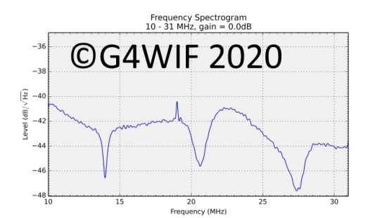
Then I tried the same test into a standard £10 TV dongle with HF converter from this company. My PC was running this software which provides a spectrum analyser display.
My spectrum analyser is set to 10dB per vertical division while the dongle vertical scale is more “stretched”. So it looks more “hilly” - but essentially, it is telling the same story.
It it clear to see that this inexpensive set up is telling me much the same thing regarding the filter response - and for considerably less cost than a spectrum analyser. Certainly it isn't the precision instrument the real spectrum analyser is, but it doesn't do a half bad job.
A while ago I built a Return Loss Bridge and just for hoots I tried shining wide band noise from a zener noise generator into it and observing the result of a test of my tri-band trapped vertical antenna with a TV dongle spectrum analyser. This is the result:
Well it worked after a fashion but of course, that fall off in signal level is due to the zener noise dropping off as frequency increases.
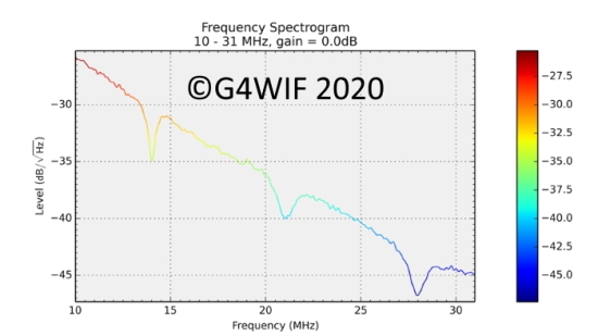
So I tried the experiment again, this time using the comb generator set to 25 kHz pulses:
This is a more useful result and while I wouldn't claim this is a measuring device, it does fall into the category of an "indicating device" - and one that provides some indication of return loss relative for each of the three bands. I'm waiting for warmer weather to work out why my antenna has shifted "LF" a bit. My antenna analyser is telling me a similar story.
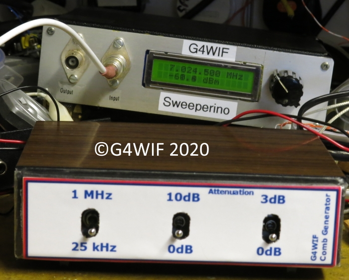
Here is a picture of the finished project on the bench with the Sweeperino.
Update April 2017
There was an interesting presentation at Baycon 2017 by Beric K6BEZ "Building your own RF Test Equipment". It's very much worth reading.
Update May 2018
You can buy a commercial calibrated comb generator from JEL for around 100 Euro. There is some application data on their website and they reference this video on youtube.
Update July 2018
Here is a very good video by Steve G0FUW showing his comb generator being used to demonstrate the effectiveness of a low pass filter.