Home
February 2020 - End Fed Half Wave Antenna
Sometimes you build something just to see how well it works - rather than because you have a need.
This was true of this new antenna. I saw some interesting videos on youtube and wondered just how well a simple antenna like the End Fed Half Wave would work.
Now this can be a very inexpensive aerial. A Nissan Micra is a very inexpensive car and it can take me to buy groceries just as well as a Rolls Royce. (not that I have one). During the writing of this article it was suggested to me that a far better aerial would be something that had the matching at the feedpoint - like an Auto ATU (for convenience) - and it probably would be better/more efficient.
My argument was that most of us don't need a Rolls Royce solution and there are many that can't justify the expense.
For explanation of how half wave antennas operate - a good place to go is the web site of Steve Yates AA5TB. Steve writes "I live on a small city lot with an HOA that prohibits antennas. However, I just take that as a challenge and though not ideal, I don't let that keep me off the air (keep scrolling). I have not been "allowed" antennas since 1984". Steve's example shows how stealthy simple wire antennas can be.
Also very informative is a "Multiband & EFHW Antenna Presentation " by Steve Ellington N4LQ
The antenna at the QTH of G4WIF
Visually, it is much easier on the eye than my faithful 30 year old doublet - which is supported by a pole at one end and the house at the other. There is also a middle support to prevent the open wire feeder sagging under the weight. It is hardly inconspicuous.
I decided that my EFHW would take the form of an "inverted L". Five metres from the shack was the stub of an old clothes line pole which is made of steel and sunk deep into the ground. This "stub" would provide somewhere to anchor the vertical section (and provide a whole lot of future misery).
 .
.
I had expected that the EFHW would be zero cost because I had loads of (what I thought were) suitable toroids to wind the 49:1 matching transformer. They weren't, and I'll cover that elsewhere.
So the cost was £7.95 for a T240-43 toroid and a trip to LIDL to buy a plastic food container to mount it in. (see below).

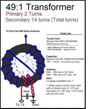
There are so many videos on Youtube showing how to wind this transformer. Most show just 14 turns tapped at the 2nd turn. Really that is all it is.
The basis for this matching arrangement is the property of half wave antennas in that at resonance they present a high impedance to the feed point. The value will vary somewhat but a figure of 2500 - 3000 ohms is a reasonable figure to work with. This will also be true of multiple harmonic frequencies of the lowest band. Hence why this is multi-band. A 49:1 transformer will bring that high impedance down to a value close to the 50 ohm coax that we often like to use.
This is an 49:1 autotransformer rather than the apparently popular device known as a 9:1 UnUn that has appeared of late.
As I started to study the EFHW it seemed like I could make a short or long version. The longer version gave me a small slither of 80m - a band I'm not really that fond of.
But I had the room, so why not go for that too?
I would have been happy to just get 40m and 20m. The realization that I could also use it on 15m and 10m was a bonus.You will notice that these bands are harmonically related. No WARC bands here.
I should point out that you can actually buy these transformers, and indeed, the whole aerial - but you are looking at something north of £50 for a transformer in a good weather proof box.
You can buy the whole antenna and the wire that they come with is probably better than what I used.
A complete antenna with the apparently respected "MyAntenna" transformer gets you into the "way over a hundred quid" region.
My wire cost £1 on a big reel from a radio rally. I should also point out that the "MyAntenna" transformer is rated at 1kW - it probably has two or more FT240-43 toroids inside whereas I just used just one and that is said to be good for 100 watts of SSB (probably less for CW). More than I will ever need.
My transformer.
This is built on a small sheet of perspex which can be easily removed from the LIDL box.

In comparison with the videos showing 49:1 transformer construction, mine seems a bit busy with terminal blocks and SMA connectors. My coax run is only 5 metres from the shack but I wanted to be able to reliably test using a Vector Network Analyser in the warm. [Why do we embark on antenna work in the dead of Winter?].
The unusual way I had wired the transformer meant that I could disconnect it from the coax and apply short, open, and load components at the box and thus move my testing reference plane to the antenna. Effectively ignoring the coax cable in my tests. The SMA at the transformer also allowed me a convenient point to test at the aerial with the NanoVNA (with the Coax unplugged). I will probably remove the SMA just in case they are upset by the presence of the occasional higher power.
Picture with kind permission of N4LQ.
My main inspiration was the vast library of videos by Steve Ellington N4LQ - and an article ("A 3 or 5 band end-fed antenna") which appeared in February 2016 Radcom by Jos PA1ZP. It is still available online for RSGB members.
Steve N4LQ has an excellent video here that shows how to wind this transformer.
There is also a great resource on Facebook in a forum hosted by Steve N4LQ.
You will notice that half way through winding the 14 turn secondary the wire passes through to the other side and then wound back the other way. I didn't find a reasonable explanation for that until I watched a video from "radio prepper" (Gil F4WBY) where he said that were you to simply just keep winding, your "hot end" (where the aerial connects) would end up right next to the earth end of the coil.
Whereas, with the conventional way people wind these 49:1 transformers, it means that the "hot end" is on the other side of the toroid than the earth. This seems to make ergonomic sense and later on I heard Steve N4LQ say pretty much the same thing in his video.
To ground or not to ground.
I'm convinced by the volume of tests conducted by N4LQ - and this one, and this one too.
In short, if you can - you should.
Description.
The radiating part of the antenna can "dog leg" around whatever space you have. As described above, I chose to use an inverted "L". The vertical radiating section was a pole from an old CB antenna (with all the impedance matching parts removed).
It was bolted to a steel pipe that was conveniently concreted into the ground from it's previous life as a clothes line (for drying) support.
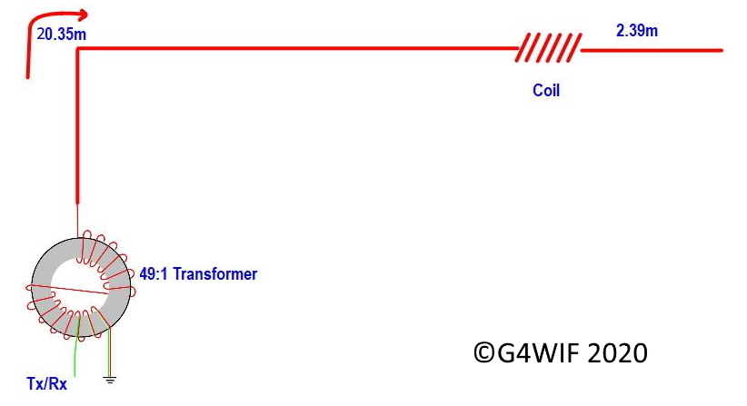
At around 5 metres above ground the horizontal part was formed of roughly 20.35m of wire, a 110uH inductor and a further 2.39m of wire.

The 110uH Inductor is shown to the left.
There have been many articles that show different details for winding this inductor.
It is perfectly reasonable that the authors used whatever formers they had and whatever wire.
I went my own way in this regard and I'll write about that perhaps in a later article. The key thing was to be able to calculate accurately and fortunately that is made possible by the free availability of Coil32 (and Coil 64). Coil32 takes all the hard work out of predicting what is needed for a particular inductance. I'm of the opinion that not all articles are to be trusted with dimensions - as one in particular came in considerably low. It may simply be a misprint on the former size. I don't want to point any fingers as otherwise the article was very helpful so I advise simply check the figures before winding.
It helps enormously if you have a tester that can verify your work. My most trusted tester is from "Almost All Digital Electronics". Sadly it is no longer available. In the same bracket is the LCR45 component tester from Peak Electronics. It has been around for a long time and gained a good reputation.
Finally, for the budget conscious, there is the ubiquitous "All-in-1 component tester transistor diode capacitor resistor inductor" which is widely available. For the money it can't be beat. Sometimes you require reliable accuracy, and sometimes it is helpful to just know that you are in the ballpark.
If you have a Vector Network Analyser like the NanoVNA, then you can use that. When I built the blue coil shown in the picture above, all the testers mentioned (except the Peak - which I don't have) agreed within a reasonable margin of the predicted value. And that's all you need in these circumstances.
Wire lengths.
In his article, Jos PA1ZP said "I never give precise wire lengths.... because velocity factor for different wire may vary up to 7%. Presumably, the height above ground and nearby obstacles will also factor in. The lengths quoted above are a rough guide. Make them longer and "snip - test" then "snip test".
About the loading coil. In his paper, Steve Nichols G0KYA said "The 110µH loading coil is used on the version for 80m. The coil effectively stops the RF current flowing in the final 2m or so of wire at 7MHz and above". So the last section is only seen when transmitting on 80m.
At this point, after all that snipping you may be expecting me to say "and it worked wonderfully" - but sadly it didn't.
This scan shows what a disappointment 20m, 15m and 10m were. It shouldn't look like that even if these were bands that I rarely use - I wanted to know the reason.

Which brings us to the reason I'm writing about something that many others have already documented - and probably better.
This is a "what went wrong" - just in case you get the same thing.
The 20m - 10m SWR was horrible and the low SWR expected on 10m simply wasn't there.
I removed the horizontal part and expected to see a nice match on 10m with just the 5m vertical section.
After all, that was it's original purpose. It was still awful. So I stretched a 5m length of wire from the matching transformer to a nearby tree. The result was gratifying - so what was wrong with the pole?
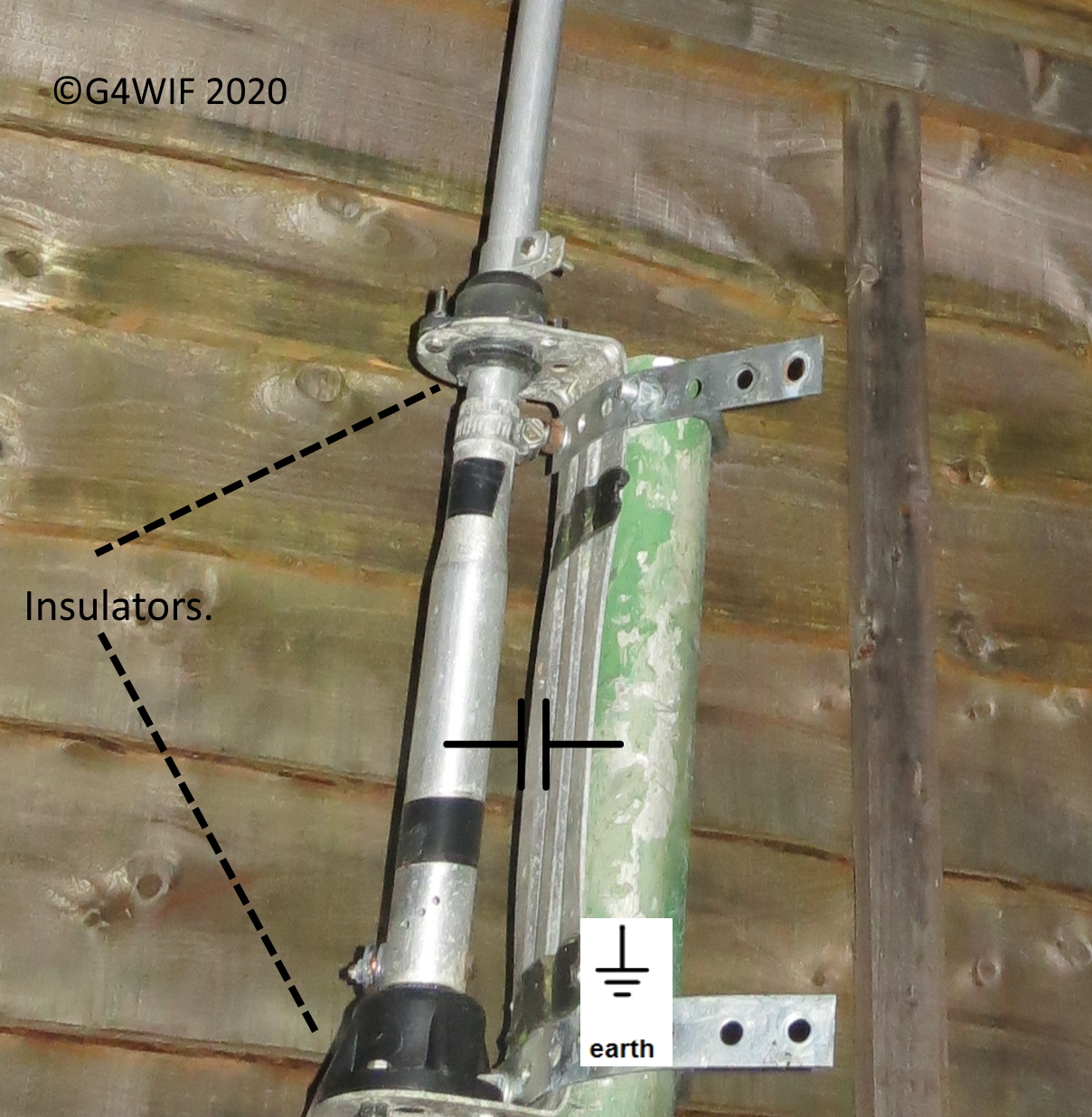 As you can see, there are insulating rings that prevent the CB Antenna being at the same potential as the green mounting pole that you see there. I removed them and just wrapped so temporary tape around instead. That made no difference. So they weren't the cause.
I assume that there must be a capacitive relationship between the two poles that skews things at higher frequency?
The CB antenna mounting plate was intended to be screwed onto a flat surface like a wall. I'm thinking that my bolting it to a pole sunk into the ground was the real issue.
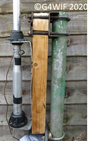
To try prove the theory, I arranged some plastic horizontal offsets (pvc pipe) that allowed a replacement length of wire to simply hang a foot away from the old CB vertical.
The CB pole was no longer part of the antenna. At the top has some rope connected that raised the horizontal wire section - which is connected to the replacement vertical wire..
The scan below shows far a better result. SWR was lower between 20m - 10m and there was actually a "dip" showing resonance on 10m.

Obviously, you can see 15m still misses the mark.
I remained curious about why 15m was "dressing to the right" a little. Could that CB pole and proximity to the green steel pole still be affecting the performance?
 This arrangement completely divorced the "U" bracket of the CB antenna from the green earthed pole.
Returning the CB pole to being the vertical section of the Inverted L did not have beneficial effects.
There was one other step I might make and that was to buy and sink a wooden fence post in the ground - well away from the green pole.
The attractive qualities of that green steel pole was that it was very solidly concreted into the ground. It would probably support the aerial whipping around in the wind - just as it had done years ago when it was taller and was used to support a clothes line.
As to the interaction with the CB pole, the only way to know was to remove it entirely and fortunately, I had a large telescopic fishing rod that could replace it for the test.
A better result.

The SWR on 20m was further reduced and the 15m (21MHz) resonance was now where it should be.
So clearly there was some interaction between the CB antenna and the green steel pole sunk into the ground. I decided to abandon the old CB pole and just use the fishing pole (which was also a little longer - just over 6 metres) to hold up the wire running between the transformer and the horizontal section.
As the shack is also quite close, I am able to retract it when it is not in use to around 4 metres so that it is not unnecessarily stressed by wind. It is a situation that works for me.

The finished installation.
There is a thin support rope at the top tied to a ground stake behind to help counter bending by the weight of the horizontal wire.
Testing on the Air.
I used the reverse beacon network. At the time of writing I have just concentrated on getting a feel for 40m. Using 5 watts CW the report suggested that I was reaching most of Europe.
Playing with numbers.
Using the data obtained from NanoVNA Saver I modeled the cable losses on 80m and 10m due to SWR. This loss is something that the ATU can do nothing about - just fool your transmitter into seeing better. I was using some reasonable Beldon RG213 cable. It is about as thick as my little finger and remember I only had a short run of 5 metres.
I was curious what the losses would be over a 50 metre run and what it might be with the really cheap RG58 coax that you can get at rallies. In the USA, Radio Shack used to sell it. I used this data with the excellent software "TL Details" which already had the specification for both cables. I used the R & X values given by the NanoVNA.
Power at load (as percentage of input)
3.5MHz (SWR 2.57)
RG213 - 5 metres in length - 96.8%
RG213 - 50 metres in length - 81.8%
RG58 (Tandy) - 5 metres in length - 93.5%
RG58 (Tandy) - 50 metres in length - 64.8%
3.6MHz - (SWR 1.14)
RG213 - 5 metres in length- 98.5%
RG213 - 50 metres in length - 87%
RG58 (Tandy) - 5 metres in length - 97.1%
RG58 (Tandy) - 50 metres in length - 75.7%
-------------------------------------------------
28.3 MHz (SWR 2.03)
RG213 - 5 metres in length - 95.2%
RG213 - 50 metres in length - 60.3%
RG58 (Tandy) - 5 metres in length - 89.3%
RG58 (Tandy) - 50 metres in length - 21%
29.6MHz (SWR 2.37)
RG213 - 5 metres in length - 94.6%
RG213 - 50 metres in length - 54.9%
RG58 (Tandy) - 5 metres in length - 87.8%
RG58 (Tandy) - 50 metres in length - 6%
I also calculated the loss at 29.6 MHz if the load was exactly matched (i.e 50+j0).
Using RG213.
The 5 metre run would deliver 96.5% to the load
The
50 metre run would deliver 69.86% to the load.
The RG58 cable under the same conditions:
The 5 metre run would deliver 92.1% to the load
The
50 metre run would deliver 44.3% to the load.
Conclusions.
Of course, loss increases with frequency and SWR. A loss you might accept with cheap cable on 80m may not be quite as acceptable on 10m. If I was constrained to a 50 metre cable run and loved 10m operation I might spring for something even better than RG213. OK, it's possibly expensive, but not as expensive as a linear amplifier.
Years ago the late LB Cebik W4RNL presented a paper to the "FDIM" conference at the Dayton Hamvention called "A dozen ways to see and love your feeders".
This paper revealed to me the properties of feeder loss versus frequency and quality. I'm not really sure who has permission from his estate to make this available. I leave you to decide where to read it.
What I suppose this shows is that my short 5 metre run could have been made using the cheap stuff and I probably wouldn't have noticed the quality. However, when you scale up to a 50 metre cable run you can see the benefit of splurging on some decent low loss cable.
Other useful information:
A very old lecture by Frank K3AW. The quality of the information outweighs that of the recording.
Everything you always wanted to know About Antennas (but were afraid to ask
Half wave antennas are mentioned - but then, all kinds of antennas are covered in this lecture.