Home
June/July - Weak Signal Propagation Reporting
Before early 2020 I had never tried WSPR. Before that was to happen the new shack computer needed to be connected to the TS2000. Just as the older one had.
That took a few days of work.
The audio side of things can simply be accomplished by using your PC sound card. The quality of sound card support varies from PC to PC. Years ago I bought the SignaLink which is a highly specified external sound card. For a while back then I had played with PSK31 and of course SSTV and Weather Fax can also be interesting to monitor. I never regretted buying the SignaLink.
For the transmitter keying on the old PC I had used a simple connection based on a parallel interface. Well of course, modern computers do not have those.
So in the world of PC's with no parallel printers, keying now is accomplished by using a USB/RS232 interface but I thought that the rig should be further isolated from the computer by using an opto-isolator. Except that I couldn't find one in the junk box and I was too impatient to wait for EBay to provide.
What I did have was 1000's of LED's and also some light dependent resistors. You can probably see where I'm going here. The RS232 interface flashed the LED. The LED illuminated the LDR. The LDR keyed the radio.
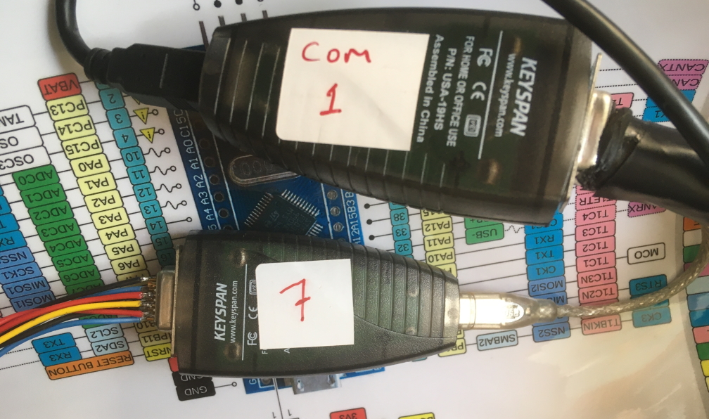
"KeySpan" RS232 to USB Adapters:
A second USB/RS232 adapter provided the CAT interface to the TS2000. Having got this far, all kinds of software can control the radio. An old (pre-commercial) Ham Radio Deluxe works very well.
So also does WSJT-X which is available from:
https://physics.princeton.edu/pulsar/K1JT/wspr.html
With the TS2000 turned right down to 5 watts CW I managed to get reverse beacon network reports from all over the world on 40 and 80.
A simple Computer to radio interface is described in a video by Charlie Morris
Charlie makes excellent tutorial videos showing his projects as they develop.
I didn't like the idea of leaving the TS2000 banging away 24 hours a day so I looked around for a very low power beacon transmitter. Fortunately, RADCOM May 2020 featured an article by Tony F4GOH. A good deal of Tony's article can also be found on his Github site. Including all the code that you need.
Tony F4GOH is a terrific designer and he freely shares his projects. He is also kind enough to answer questions when you get stuck.
With that kind of pedigree this was the project that I elected to build.
It was also a good choice because everything I needed was already in my junkbox.
Well everything except the BS170 Mosfets that Tony uses. But I had something similar, and it's part of the fun to adapt. So I used 2N7000 mosfets.
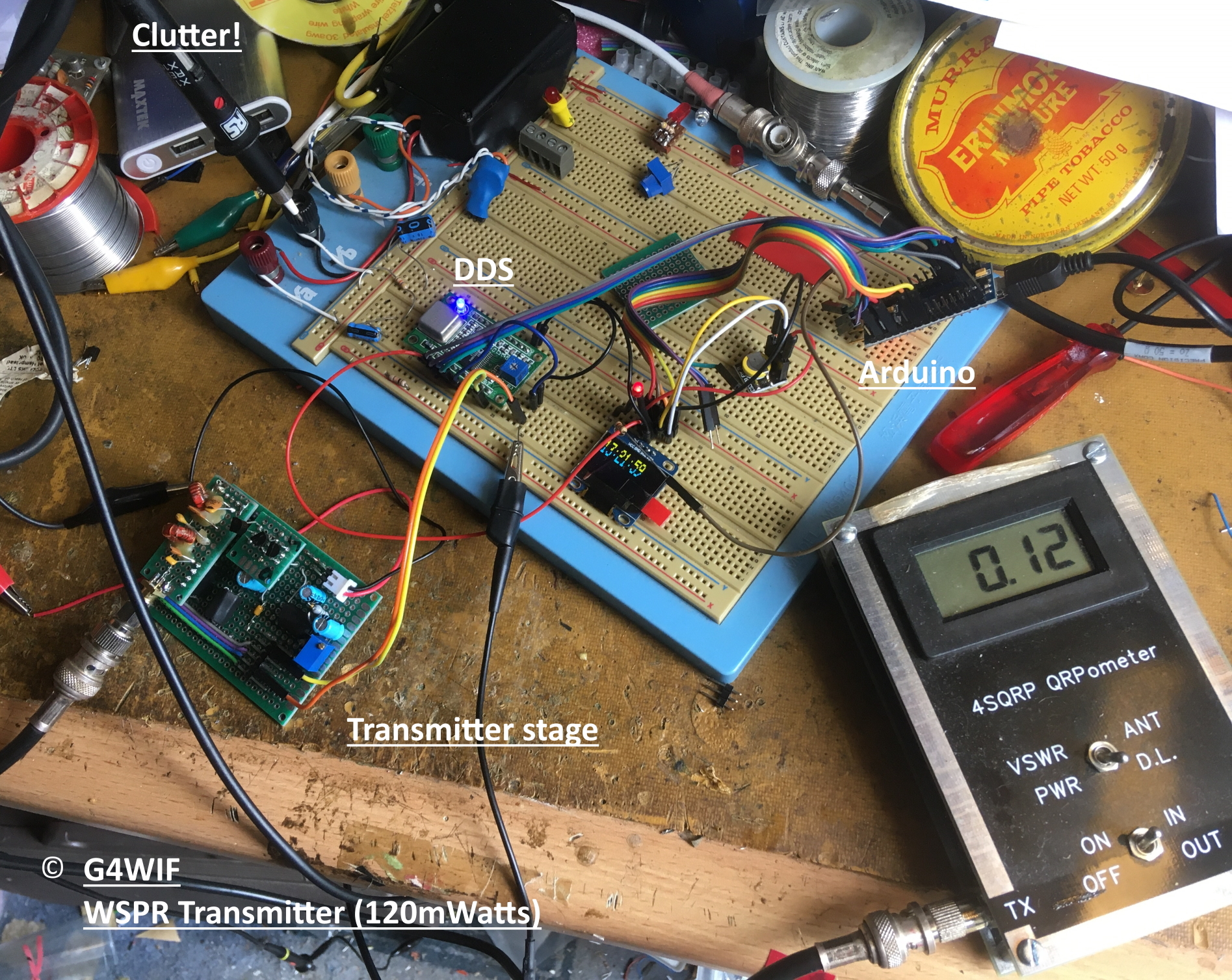
The first step was to breadboard the logic side of things. So DDS, Arduino, Real time clock and tiny display were connected together using jumpers.
Here is a photo of the working project before it made it to a circuit board:
Then to load the sketch into the ardunio IDE and then upload it to the "nano".
It didn't work of course. Things never do.
The new computer didn't have the IDE installed so I had downloaded the latest version. I was getting all kinds of errors concerning libraries.
After dragging the old computer out of the junk pile it all went swimmingly well. Sometimes it appears that older libraries don't like to work with newer IDE's. Whether this was it - or just dumb luck, I don't know but installing the old IDE on the new computer fixed the issue.
Maybe if I had sacrificed a chicken first? Who knows.....
I was a tad confused as to why Tony specifies a DS3231 RTC module but used a DS3232RTC library. An email to Tony received a quick reply that there are all kinds of useful things in that library that work with the DS3231. I was also confused as to whether I had ordered the correct RTC module. Some of his website pictures show one type and the other, a smaller version.
Apparently you can use either. Mine were just under £10 from Amazon and for that you get five of them!
Once the RTC has been set up with the correct time it will output to the display but freeze when the beacon is transmitting. Tony told me that timing was an issue and without using interrupts, updating the display and sending the WSPR sequence would have been difficult.
Tony also provides in his design an LED to flash and show that the beacon is active transmitting.
This stumped me for a while. I had connected the LED just as shown in Tony's Fritzing drawing. Only he shows the LED connected to the arduino pin D2, but his code (when I checked it) has it going to pin D8. This may have been corrected by the time that you read Tony's documentation.
At this point I want to make clear that this is no criticism of Tony or any author that shares his designs with the community completely for free. We all make mistakes and this is a learning hobby.
My beacon was transmitting. There was no RF being supplied to an RF amplifier because I hadn't built that yet. Because I have the TS2000 set up to receive WSPR I could see that the tiny signal being radiated from the breadboard was being received, albeit just over a few feet.
Initially I built the transmitter stage exactly as described by Tony but it didn't work for me. Tony had said in the RADCOM article that the WSPR signal was available from both the square wave output and the sine wave output of the DDS. He had used the square wave and I am assuming that this was with DC levels that supplied bias to the gates of his BS170.
But my DDS had no signal on the square wave output. Plenty though on the sine wave output. Maybe it was a duff DDS module and so I tried a spare but there was no change. I'm just going to assume that I missed a step and caused the square wave output method not to work. Many others have got this working!
But I had my solution. Use the sine wave and provide my own bias - and Tony briefly described this alternative in the Radcom article - but I needed more detail how to do this.
While discussing this with my friend (and often home brew collaborator) Nick G8INE, he suggested that I take a leaf out of the genius handbook of Hans Summers, G0UPL. This is the link to one of his projects.
http://www.qrp-labs.com/images/ultimate3s/assembly_u3s_r3_a4.pdf
So that's what I added - and it works - just as Hans describes in his excellent document.
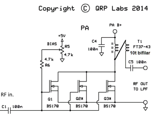
Each module was mounted onto perfboard to make a more rugged unit. Below you can see a blue trimmer pot which adjusts the bias - just as shown in the above schematic.
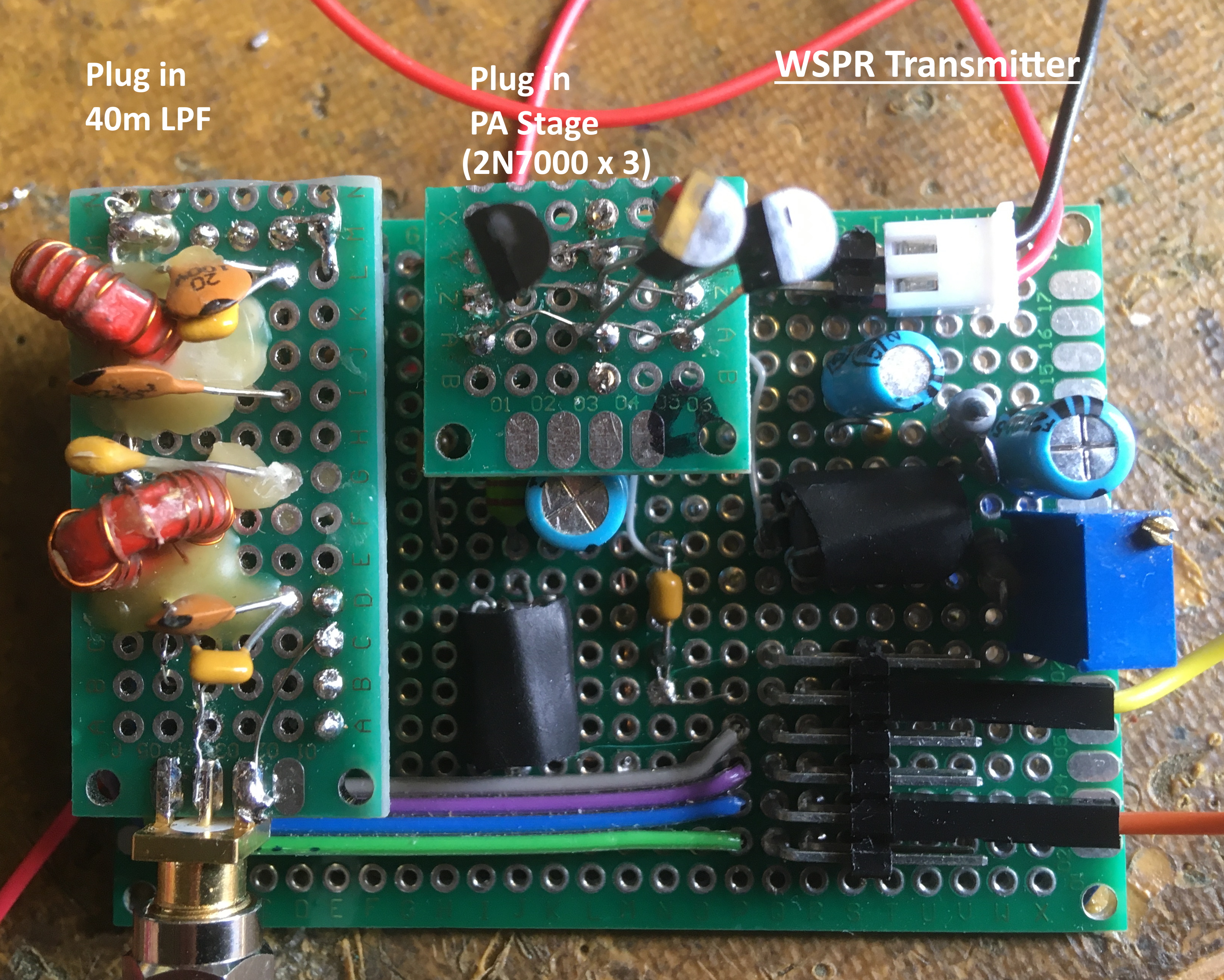
A few 2N7000 Fets gave up their smoke during the build, and as good as those perfboards are, you can't get away with resoldering forever. To start with I used a small piece of board to mount them onto pins that are on the main board - but later simplified the module like this:
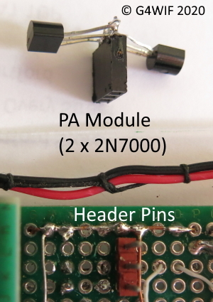
I had started with three Fets in the PA but later reduced it to just two. The trimmer pot adjustment procedure is very well explained in Han's document. Three Fets gave me a little over 120 milli-watts. Two comfortably produced 100 milli-watts.
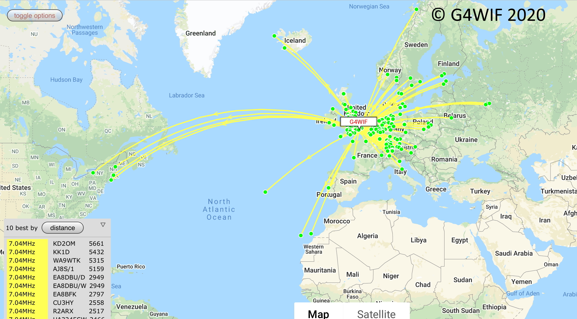
It was time to leave the transmitter broadcasting for a long period. Here are the pleasing results:
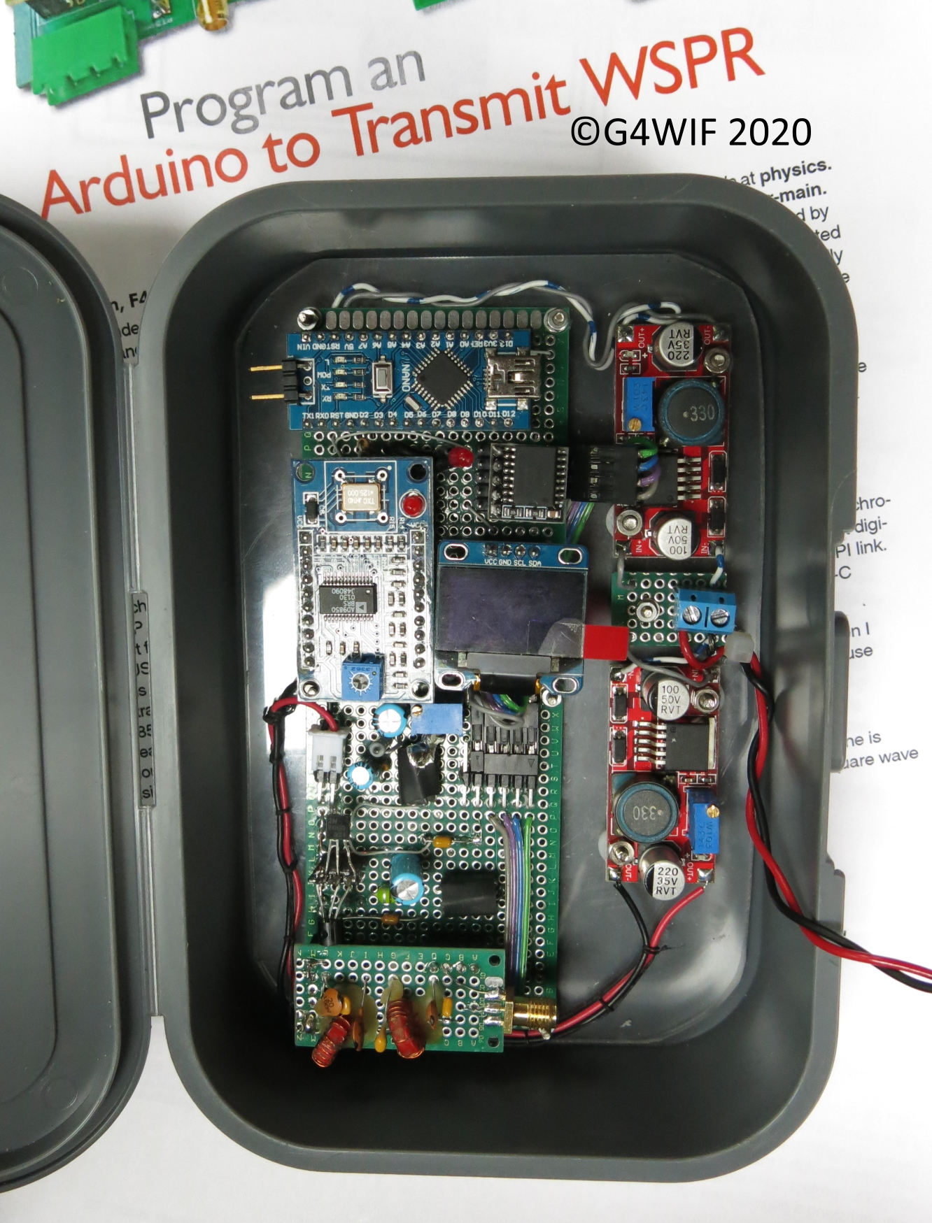
The next task was to go from breadboard to a cased project. Or in my case, a "sandwich boxed project". The grocery chain LIDL is a mecca for homebrewers. Often there are good quality tools on special offer, and sandwich boxes make a good way to ruggeddise a project. Firstly all of the modules were mounted onto a perspex sheet.
You may be wondering why there are two buck convertors on the right hand side. One is providing 7 volts for the arduino (which then has its own internal 5v regulator). The other buck convertor is set to 5 volts for the PA stage. The arduino internal regulator does not have the capacity to supply the whole project. In a conversation with a blog visitor it was said that these buck convertors produce switching noise, and they do (a little) - but in my tests I haven't found it to be a huge problem. What I like about them is that they do not produce heat like linear regulators, they are adjustable and they are inexpensive!
![]()
.... then the Perspex sheet drops into the sandwich box.
My thanks to Tony F4GOH for coming up with the design and for generously sharing it with the community.
Later news....
Tony's article appeared again in revised form on page 20 of the August 2020 QST
Having the opportunity to work further on the project, Tony improved the article even further.
In August 2020 Tony informed me that there was a new version of his software and now it included RTTY and PSK31. See his Github to keep up to date.
If at this point you still feel like trying WSPR but would rather have a kit - then you can't do much better than Hans's Ultimate 3.
Additional reading provided by Nick G8INE:
https://www.qsl.net/va3iul/Bias/Bias_Circuits_for_RF_Devices.pdf
October 2021: