Home
August 2019 - A Digital Attenuator
Tony Jaques G3PTD and I started to exchange emails about this back in March. We had both seen a video on Youtube that had piqued our interest about a cheap PE4302 module costing around ten pounds.
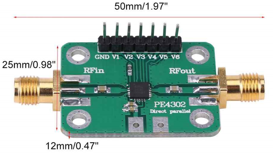
The PE4302 module offered amazing performance. It promised 31.5 dB attenuation range in 0.5 dB steps. 50 ohm impedance. DC to 4GHz.
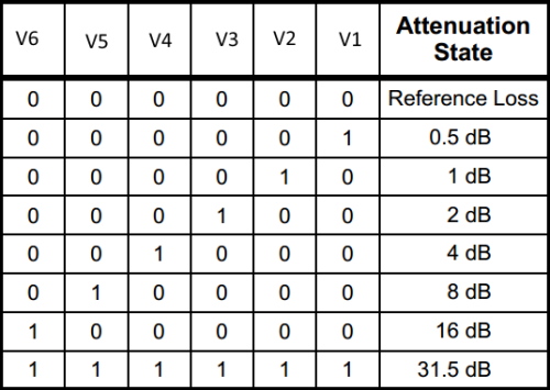
The attenuation is set by a combination of “highs” and “lows” placed on the V1 – V6 pins. You could simply use switches and consult a table - but we were attracted to a rotary control and digital display.
As the object code was available, we each constructed the design from the youtube video– but we had discovered some slight bugs which we couldn’t therefore fix because the source code was not made available. Tony G3PTD decided to code his own.
I’ve built switched attenuators from various designs and the problem has always been the inaccuracies due to inadequate screening and preferred resistor values - which tend to wander a bit at higher frequencies because they also have reactance. Later, Tony and I were to measure the module attenuation to be within 0.3 dB of the value that was stated on our displays - virtually flat over 100 MHz (and beyond). Not bad for around £10.
Most of the following is the design of Tony G3PTD with some very elegant code using an Arduino Uno (or Nano) to control an LCD Display. Some batting back and forth of ideas between us bought about some changes and we probably spent quite a lot of time on the project. But this kind of thing can become an obsession!
The circuit diagram of (one of) the final design(s) is shown below.
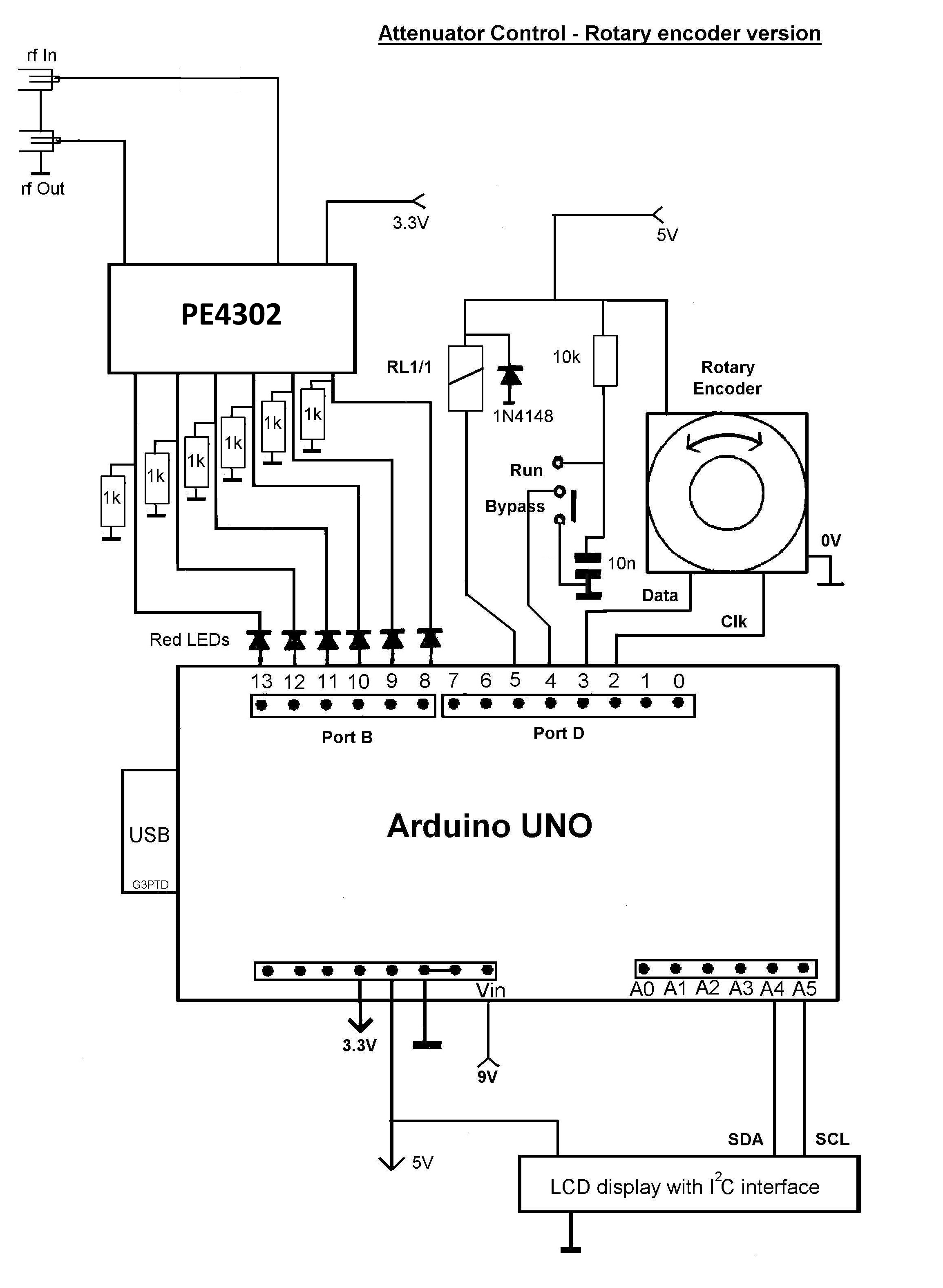
The red LED’s provide two functions. Because the attenuator module is a 3.3v device, they drop the voltage out of the 5v Arduino to an acceptable level. With the addition of the 1k grounding resistors they provide a perfect visual diagnostic that shows when turning the rotary encoder that the binary output is advancing.
Resistors are also provided built into the attenuator module - but then it would need to be connected and this addition allows the building and testing in stages. With the values chosen it all works together with both sets in parallel when finished.
I should explain the “run/bypass” switch. We had read that the module was specified on the data sheet with 1.5dB insertion loss. Tony’s original circuit and code allowed the operation of an inexpensive relay which would take the attenuator out of circuit. When the switch was operated the display would show “bypassed”.
We both have pretty respectable Vector Network Analysers and the 1.5dB insertion loss was confirmed. What we also confirmed was that the relays made rather a mess of the flat performance that I mentioned above. If you have some decent (usually expensive) coaxial relays you may see a different result. So we’ve left that in the code.
So ultimately, we decided that a device that provided attenuation from 1.5dB – 33db (including the insertion loss) wasn’t a bad thing and if we wanted 0dB attenuation, then we could replace the unit with a short cable!
I will explain now why there was more than one final design.
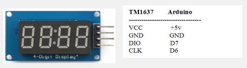
Tony G3PTD liked the LCD display but I had discovered the wonderfully cheap 4 digit TM1637 display and ordered a few to play with. It seemed to me that the LCD was rather a waste when you only need three digits – and getting the TM1637 working it was both fun - and at times frustrating!
These displays are not brilliantly documented and you have to search around a bit to understand how to program them. It even took me three hours to get the centre colon LED’s to light - and if you actually just want a decimal point a blob of paint over the top LED seemed to be the accepted solution!
This rough and ready Youtube video shows that my modified code allows both the original LCD to work with the LED also attached. I got my display from both Amazon and here in the uk.
Tony G3PTD and I ran loads of tests over the months, but here is a scan of 1 – 100MHz showing pretty flat performance.
With my display showing 30dB. The attenuation measured here (at 94MHz) was 29.723dB and pretty much the same result over the whole 100MHz scan.
We both feel that some good additional screening around the PE4302 module would be advisable. The code for both versions (and more photos) will be available from the Sprat page of the club website.
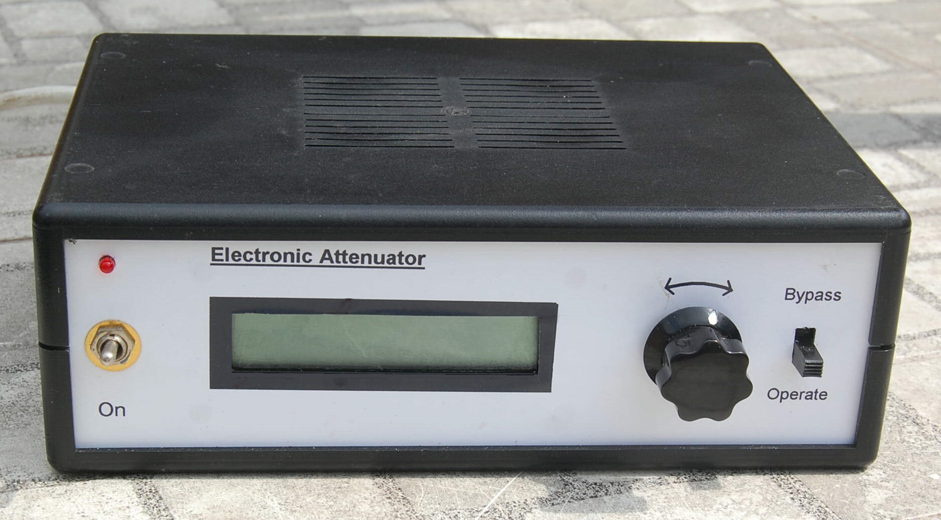
Here is a photo of Tony G3PTD's finished bench test equipment.
My version will be used inside another item of test gear (more about that later).
This explains why it is currently uncased.
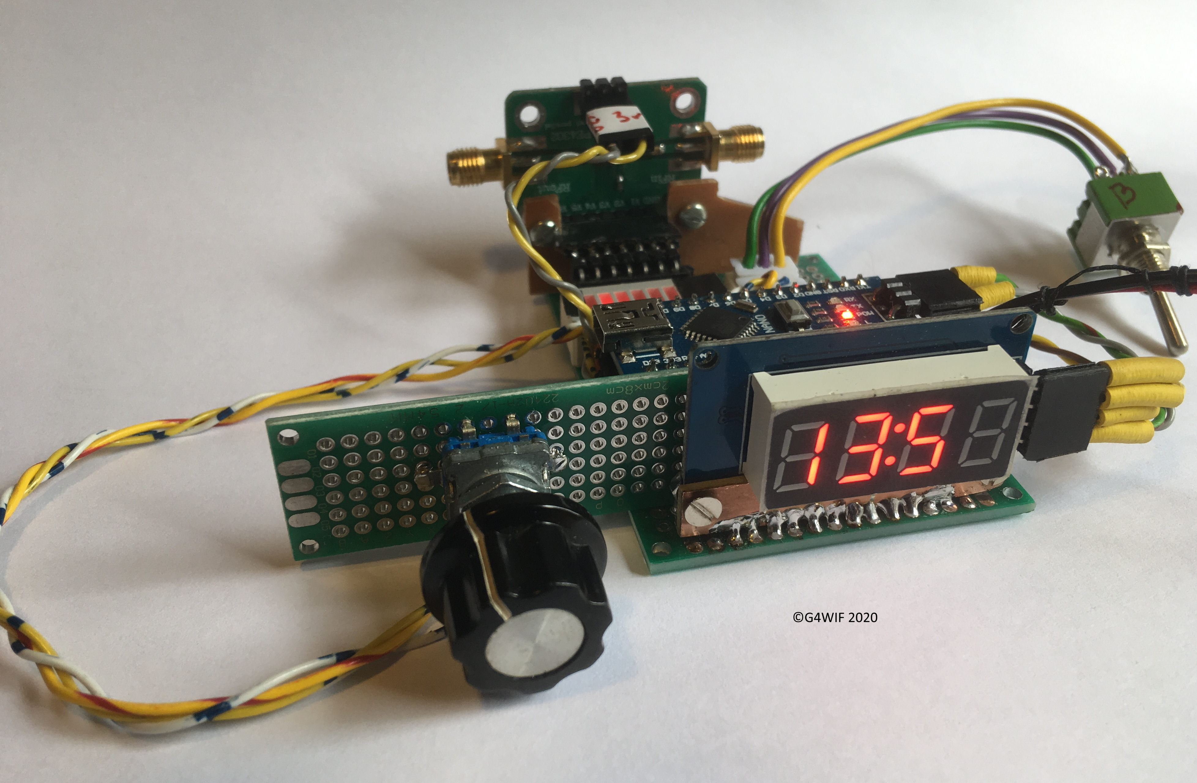
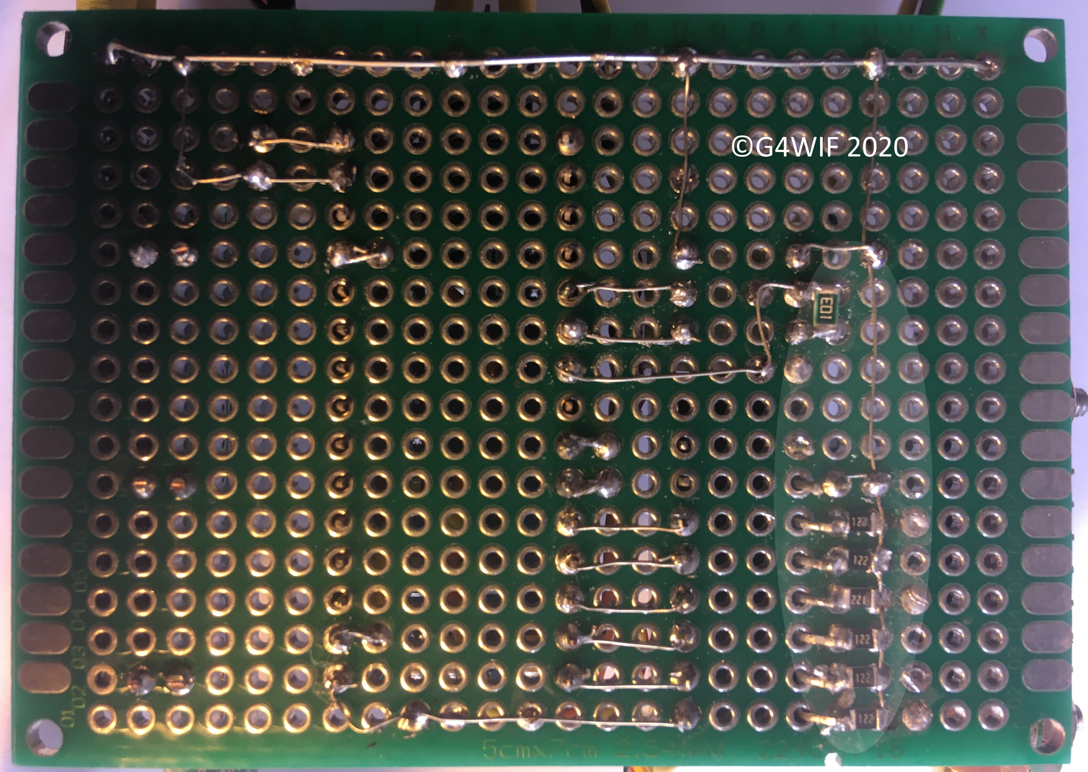
As you can see from the above, I used perfboard. This is very cheap to buy and the holes are plated through. As is evident, it does not always become a thing of beauty, but it works and saves on PCB design. It also lends itself very well to the use of surface mount components. (see lower right).
You can imagine the same thing with leaded resistors would have taken much more room.
Code:
Here is the sketch by Tony G3PTD. You can see that he has included some very helpful comments inside. This is what you would use if you only needed an LCD display.
Here is my version which supports the LED display. I have left Tony's LCD code untouched. So as demonstrated in the video mentioned above, both displays will work at the same time.
Acknowledgements:
I'm not a competent enough coder to have built this from scratch as well as Tony G3PTD did.
I appreciated Tony allowing me along for the ride and the fun that we had collaborating on the project.
References:
Tony G3PTD tends to create a manual for any completed project. This is his manual for the attenuator.
Practical Electronics ran a brilliant four page article in June 2019. Everything that you probably want to know was contained in those pages. It would be worth buying the back issue just for that article.
Practical Electronics in the UK seems to feed off a similar magazine in Australia and the article appeared there in 2018.
Here is a link to their site which shows a free sample of the first page of the article.
Tony G3PTD used an Arduino Uno and I used a Nano. The circuit diagram above is for a Uno.
These two datasheets show pretty clearly the pin outs for the two devices (Uno and Nano).
Another great reference is the Blog of DuWayne KV4QB who has used two of these modules to create a 64 step attenuator.